Industry solution

Semiconductor Ultrapure Water

High-purity generation and polishing concepts for electronics manufacturing, rinsing and precision processes.

Discuss Your Water Requirements

Application risks

Identify what can change the design.

  • Ionic load entering the high-purity generation train
  • Silica and carbon dioxide that affect RO and EDI performance
  • Particles, organics and microorganisms introduced by storage or distribution
  • Variable demand and stagnation in the high-purity loop

Treatment objective

Agree the target at the actual use point.

  • Process-owner limits for conductivity or resistivity
  • Defined particle and organic-carbon limits where relevant
  • Microbial control strategy for storage and distribution
  • Monitoring points tied to the process risk rather than a generic grade label

Recommended route

Translate the application into a treatment sequence.

The final sequence depends on the submitted water analysis and operating inputs.

  1. 01

    Stabilize the feed with filtration, chlorine control and hardness management

  2. 02

    Reduce ionic load with one or two RO passes according to the approved basis

  3. 03

    Use EDI or another polishing stage only with suitable RO permeate

  4. 04

    Design storage, recirculation, UV or terminal filtration around the point-of-use risk

Sizing basis

Point-of-use peak flow and return-loop demand

Continuous versus batch production profile

Duty/standby generation and storage requirements

Design inputs

Data required before equipment selection.

  • Complete feed-water chemistry including silica, alkalinity and carbon dioxide where available
  • Quality limits at each point of use, not only at the generation skid
  • Peak flow, loop return flow, operating schedule and allowable downtime
  • Required online instruments, alarms, sampling points and distribution materials

Main components

Components considered for this application.

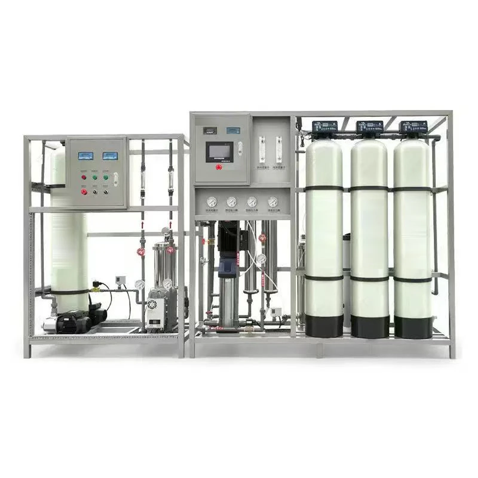
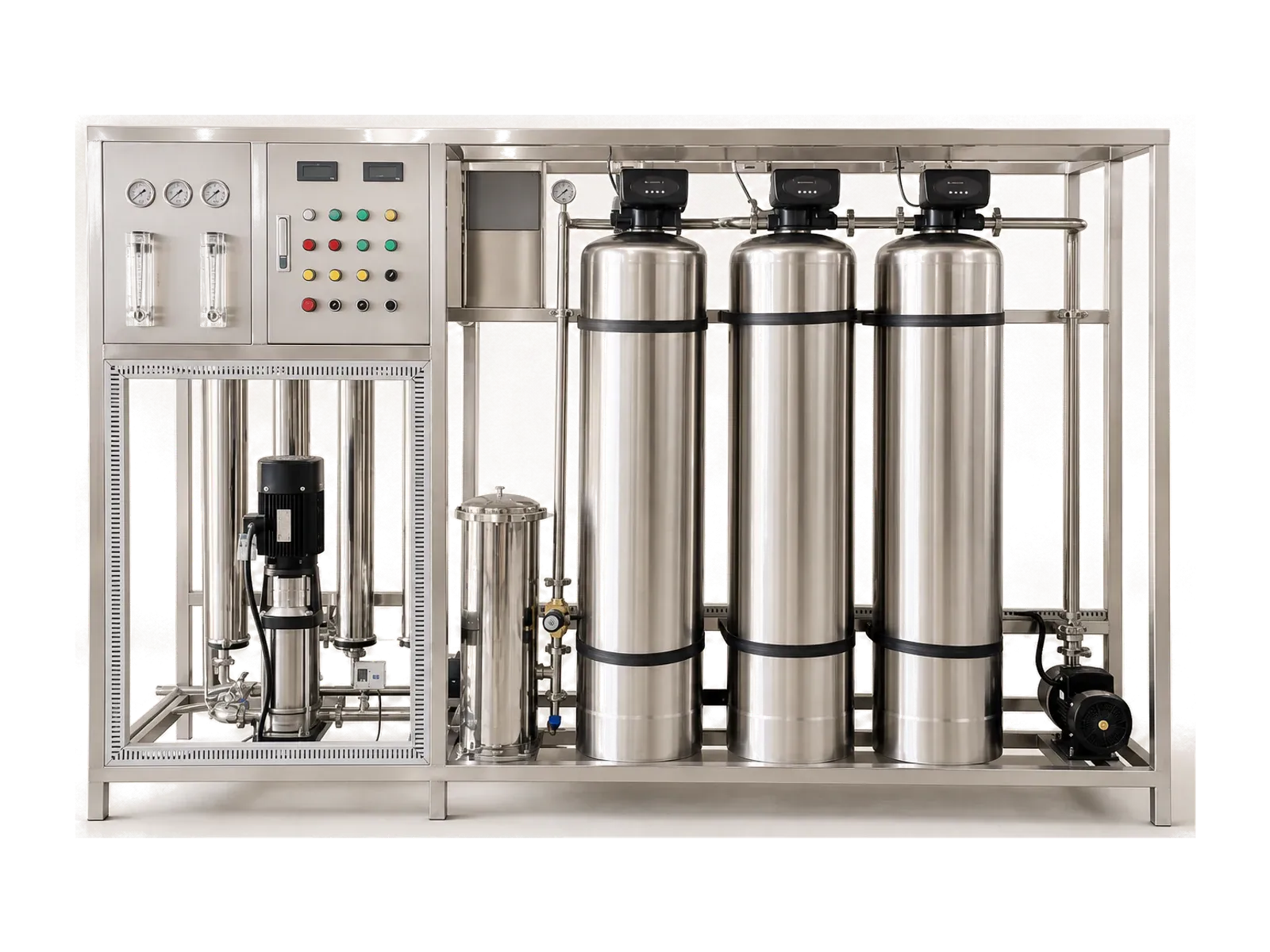
  • Controlled pretreatment and cartridge filtration
  • Double-pass RO when justified by the ionic-load target
  • EDI or alternative polishing stage with suitable feed conditions
  • High-purity storage, recirculation and application-specific terminal treatment

Scope controls

Items to confirm before final selection.

  • Resistivity, particle, TOC and microbial targets require an approved design basis and validation plan.
  • Distribution-loop materials and operating discipline can determine point-of-use quality as much as the generation skid.
  • Final polishing, monitoring and sanitization depend on the process tool and facility protocol.

Equipment components

Review system families against the design inputs.

RFQ preparation

Send the data that controls this application.

These inputs let the equipment scope be checked against the real use point.

  • Feed-water chemistry and seasonal range
  • Point-of-use quality specification and monitoring method
  • Generation flow, loop flow, operating hours and redundancy
  • Distribution length, materials, storage and validation expectations

FAQ

Questions about semiconductor ultrapure water.

Why must semiconductor water quality be specified at the point of use?

Storage and distribution can add ions, particles, organics or microorganisms after generation. The process limit and sampling location therefore need to be defined together.

When is double-pass RO considered before EDI?

It is considered when a lower and more stable ionic load is needed for the polishing stage, subject to feed chemistry, recovery, carbon dioxide and the approved quality target.

What should be included in an electronics ultrapure-water inquiry?

Provide feed analysis, point-of-use limits, flow profile, loop details, materials, monitoring points, utilities, redundancy and the process owner’s validation expectations.

Start with your water conditions

Need a system configured around your application?

Share your application, feed-water source and required capacity. We will shape the treatment process, equipment scope and options around your project.